Interserve - Linac Bunker, Southampton General Hospital
- chacker23
- Nov 3, 2021
- 6 min read
The Linac Bunker was built for Southampton General Hospital (SGH), within an operational
car park, by Interserve, the Principal Contractor.
The Structural Engineers were ARUP who were provided with specialist technical support
from the Head of Radiotherapy Physics at SGH. Stephenson RC Frames were the specialist
concrete contractor and the concrete supplier was Hope from the Breedon Group.

Project Challenges
Listed are the challenges we overcame;
Pour size and the delivery logistics to a busy Hospital and car park
Concrete mix design & production of a Test Block to confirm compliance
Radiation pathways through cracks and no sleeved ties
Concrete curing and temperature control during curing
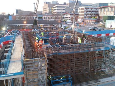
The reinforced concrete construction has walls of varying thickness from 650mm to 2730mm and were 4500mm in height. The roof slab also has varying depths from 1120mm to 2350mm. The foundations are 1000mm deep rafts, split into 3no. sections the largest on which the bunker is supported is approximately 400m3.
The bunker is effectively a concrete box within which a MR scanner is situated.
The thickness of the surrounding concrete walls and roof were made from a concrete that had to meet specific requirements to prevent radiation breakout, which would harm the public outside, when the scanner was in use.
The concrete had to have a minimum specific dry density
The concrete had to achieve a specified strength and have a low heat of hydration, to mitigate shrinkage cracks
The internal temperature of the concrete should not exceed 65°C and the differential temperature between the core and the external temperature should not exceed 20°C to mitigate cracking due to thermal shock
No tie bolts sleeves were allowed through the walls
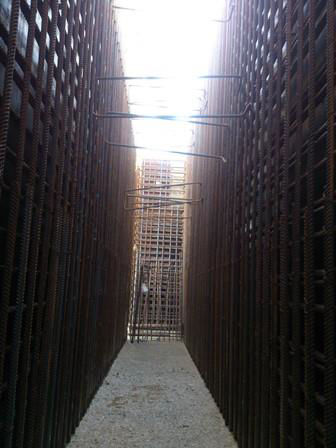
The walls were heavily reinforced to shield against radiation
Concrete Mix
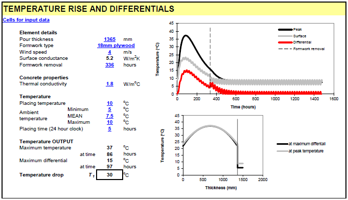
In an effort to meet the specification Hope Concrete produced a desk top study for a mix to meet the design parameters. The expected temperature rises in the 1365mm thick wall, 2310mm thick wall and the 2730mm thick wall are as follows.
The 1365mm wall the peak temperature will be 37’C at 86hrs with the maximum differential of 15’C at 97hrs. This is based on the mean ambient temperature being 7.5’C during curing.
The 2310mm thick wall will have a peak temperature of 49’C at 147hrs and a maximum temperature differential of 20’C at 170hrs. This is based on the mean ambient temperature of 15’C.
The 2730mm wall will have a peak temperature of 52’C at 169hrs and a maximum temperature differential of 20’C at 193hrs. This is based on the mean ambient temperature during curing of 22.5’C.
The mix design is based on a 70% GGBS blended mix. A typical differential graph is attached for the 1365mm wall thicknesses.
Since radiation travels in a straight line the introduction of construction joints and shrinkage cracks caused by the heat of hydration from the concrete mix during curing are potential pathways for the radiation through the wall.
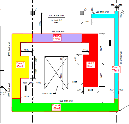
Construction joints can be managed by the introduction of toggles in the joint. However, due to the extended time the shutters would have to remain in place to control curing and the temperature gains, and subsequent difficulties in the removal of the grout loss from around the rebar at the construction joints and with the pre-preparation works for the next pour. The pour sizes for the walls were increased which also helped with the programme. However, this presented logistical challenges with the concrete pour durations and supply. See below Pours 1, 2, 3 & 4 were combined to create a wall pour of 329m3 approx.
Logistic Challenge
The foundation slab with an approx. pour size 330m3 was used to resolve any issues with the delivery to site and the traffic management of the trucks the extract below relates to the method adopted. The concrete was a standard mix
Concrete Supply by the Breedon Group (Hope Concrete) using only 8m3 lorries from a Plant capable of producing 600m3 /day, 3 miles distance from the Linac site. A contingency plant at Portsmouth is available in the event of breakdown
Lorries will be batched and held in a holding area offsite and called in using a radio by a Hope’s Senior Technician Mike Williams, who will check the concrete for workability etc. at the point of discharge
Interserve have arranged to take parking bays for a dedicated route for concrete trucks to the Linac site entrance and an area for truck washout using a Siltbuster and a skip lined with polythene. The road and any adjacent areas will be protected with polythene
The entrance to site will be made wider to allow 2 trucks to back onto each of the pumps so that they will be pumping simultaneously.
The pump details for the 2 no 39m pumps supplied by Wright Minimix Ltd are in a separate document. Providing Pump operator RAMS and the outrigger loadings and centres, together with the temp works engineers design for the pads for the outrigger loads
Stephenson will provide additional labour to manage the traffic marshalling prior to the pour to avoid unplanned parking and the traffic flow and pedestrians during the pour to ensure they do not encroach into the working areas during the pour.
Risk Contingency Plan
Concrete supply is covered by having a secondary plant
Pump failure 1 pump will be able to complete the pour
2no high frequency electric vibrators are required with a 3rd and 4th as backup in case of failure
Power supply failure. A stand by generator will be provided by Interserve.
Weather forecast. To be reviewed prior to the planned date to ensure that the batching and placing is carried out above 5°C The areas will be tented with possible heating prior to the pour, to mitigate overnight temperature cooling.
In the event, that any of the above standby measure fail. The concrete within the pour will be levelled, shaped and finished to allow a retarder to be sprayed on the surface to allow the pour to be finished later. Prior to this the surface will be cleaned and prepared for the subsequent layer
The rebar will be protected from retarder overspray by polythene sheeting. A final decision on the actual method will be determined by at which level the pour ceases. The principle has been agreed with Arup. However, this is an option that will only be implemented when all other means to continue with the pour have been exhausted.
Wall Tie Bolts and filling of bolt holes
Stephenson along with the radiology department at Southampton General Hospital came up with a method in which the tie bolts could be used minimising the risk of radiation leakage during use. The tie bolt detail was successful in serving its purpose and the method used has now passed the radiation tests recently carried out.

The lower section of bolt is unsleeved and will be left in the concrete. The sleeved element will be removed when striking the shutters. The cement fibre sleeve will then be drilled out and the hole packed with an injected repair mortar and then aesthetically finished with a cosmetic repair mortar.
Concrete Test Block
Objective
The purpose of constructing a trial block on site was to determine if the desktop calculations by Hope for the max core temperature approx. 52°C. is exceeded. Arup in their spec have stated a max core temp of 65°C.
Mix Design
The mix design for the concrete was 70% GGBS Blended mix. This mix was specified in order to keep the hydration temperature down as low as possible.
Prior to the Pour
A box shutter was constructed 2.7m high by 2.4m wide by 2.4m deep. Thermocouples were introduced to measure the temperature at various locations prior to the pour and after placing the concrete.
Thermocouples were introduces into the centre of the test block as well as nearer the face so that the differential could be accurately monitored.
A Monoflex tent has been erected around the shutter and the interior, heated using electric fan heaters from Andrews Sykes type DE25 T air flow (max 250 m3/hr) with a nominal heating duty of 2.8kW
On Site Recordings
Tests | Lorry 1 (11:45am) | Lorry 2 (13:05pm) | Lorry 3 (14:15pm) |
Slump Height (mm) | 120 | 110 | 90 |
Concrete Temperature (°c) | 15 | 14 | 14 |
Mass of concrete (kg) | 20.652 | 20.652 | 20.437 |
Mass of cylinder (kg) | 4.033 | 4.033 | 4.033 |
Volume of cylinder (m3) | 0.006942 | 0.006942 | 0.006942 |
Density (kg/m3) | 2394 | 2394 | 2363 |
Post Pour Temperature Monitoring
Once poured the temperature was monitored using a 4no Terminal recorder
Initially the core temperature was found to be lower than the external temperature this was found to be due to a defective connector terminal
It was noted that wind loads and the opening of the entrance had an influence on the stability of the temperatures inside. This can be seen on the temperature fluctuations externally & inside the tent
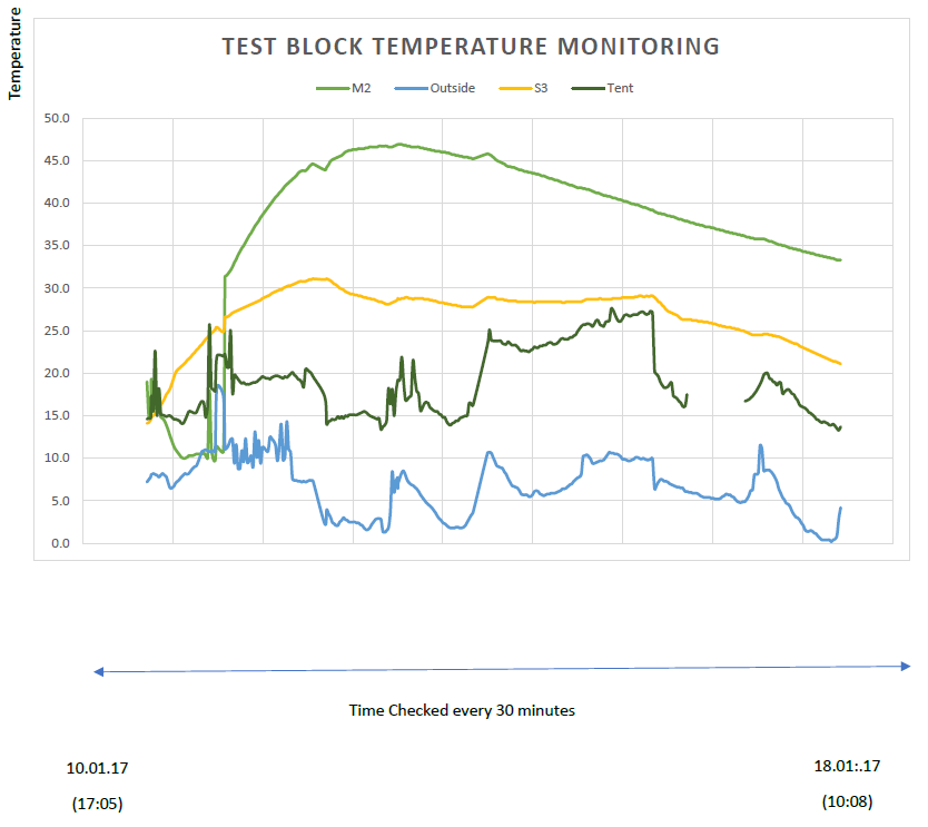
The readings plotted on the graph below; are for the period 10/1/17 to 18/1/17
The readings are taken over a 24hour period at ½ hour intervals
Additional records were maintained during the day shift
Conclusions
The maximum temperature recorded was found to be 47°C In line with the desktop study
The maximum differential of 20°C between the core and outer face was maintained
The fluctuations of the external and internal temperatures can be accounted for the wind and entrance sheeting. However, the temperature curves for the concrete were smoother indicating steady curing with no major thermal shocks.
The number of standby heaters will need to be monitored & controlled as the temperatures during the day and night can vary significantly.
Thermocouple M2 was positioned in the centre of the test block, S3 was positioned near the surface of the concrete within the block.
Inside the wall - Pre pour
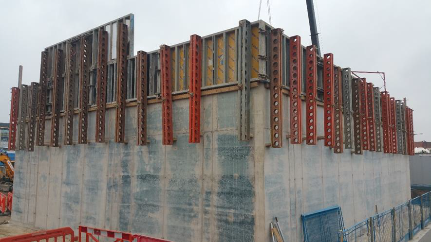
Roof Slab edge shutters. Slab depth 1200mm with an additional 1200mm for the high radiation impact zone


Comments